Transfer strategies for machine, other inrush loads

By James M. Daley, PE, ASCO Power Technologies
Contents
Abstract
Background
Motor load
The transformer
Adjustable speed drives
Conclusions
Editor's Note: This technical paper on load transfer strategies by John M. Daley of ASCO Power Technologies represents the first of several by Daley and others at ASCO and Leibert, members of the Emerson Power Network. It also represents the first technical paper to appear in Power Online's new section—Technical Papers, which will feature a healthy amount of discourse on a variety of technical issues facing the power generation industry by authors from companies and organizations around the world. So, stay tuned. ACM
Abstract
Changes in the profile of critical loads challenge the traditional concept of load transfer, the double throw switch. Concerns have been raised over the suitability of this concept for reliable transfer of running motors and other inrush loads. A position is taken that these loads must be shut down for transfer between live sources to avoid power system disturbances and equipment damage. Such actions are counterproductive and disruptive to facility operations. This paper presents the results of an investigation into the characteristics of inrush electrical loads in a load transfer strategy. It verifies the validity of the traditional transfer concept. (Back to top)
Background
Automation and technology affect the commercial and industrial environment. Their impact is felt most conspicuously in the need for quality and continuity of electric power. As a result, the scope of loads considered critical enough to warrant emergency power support has expanded. The critical load profile now includes machine loads, coordinated processes, uninterruptable power systems, adjustable frequency drives and distribution transformers in addition to the traditional loads. Each of these loads bring their special needs to the design considerations for the alternate power system, not the least of which centers on a proper load transfer strategy.
In bringing these considerations into perspective, one must be mindful of the equipment performance on the utility derived service. If the transfer strategy imposes no more burden on these loads than that imposed by operation on the utility derived service, successful operation and the desired performance will be achieved.
Investigations into the actual electrical environment of equipment operating on utility derived services have been conducted in recent years. It has been found that disruptions of up to five cycles are an expected environment on utility derived services. These disruptions are the result of protective device responses to faults and switching operations on the system.
Depending on the proximity of the fault on the system to the running motor, the magnitude of the resulting voltage reduction will vary. Such disturbances randomly occur throughout normal operation. This work has shown that off times of 2 to 3 cycles or less have minimal impact on running motors.
It has also been found that ASDs, adjustable speed drives, can successfully ride through interruptions of up to 5 cycles. If a load can tolerate these 2 to 5 cycle disturbances in the normal environment, this author proposes that it can tolerate a properly orchestrated open transition transfer having a 2 to 3 cycle open transition time.
Motors are not the only loads that require consideration for transfer. Transformers are an inrush load with a peculiar characteristic. The impact of transformer load transfer is more disruptive to the source than it is to the load. This whole issue of inrush load transfer is more readily orchestrated with the advent of microprocessor based control strategies.
Software can be written and implemented to match the transfer operation to the needs of the various loads and power systems. A suitable approach to the transfer of inrush loads is to analyze them individually. Therefore, this discussion begins with the motor load. Then, it examines the transformer and finally, the ASD. (Back to top)
Motor load
A unique characteristic of the motor load is that it stores energy in its field while the motor is running. This energy is released to the system whenever a reduction in voltage occurs at the motor terminals. This reduction could be the result of a fault on the system, load inrush to a parallel load, disconnect of the running motor or other switching operations.
During normal operation, when the motor is disconnected and after the arc of disconnection is extinguished, any energy remaining in the field is manifested back EMF at the terminals of the motor and is dissipated in the motor coast down. Therefore, whenever the motor is transferred between two live power sources, retransfer to normal after restoration or transfer and retransfer to the alternate source for testing or load demand abatement, this back EMF must be accounted for.
Failure to account for it can result in loss of load, power system disturbance and possibly damage to the motor system. Reconnection of the running motor to a viable power source before the back EMF has sufficiently dissipated must be done in phase.
An alternate means of transferring is to disconnect the motor, let the back EMF decay, transfer the motor and then restart it. The problem with this scenario is that it increases the starting duty on the motor and mechanical load. Further, given the propensity for motors to be operating in process environments, motor shut down requires complete process shutdown and restart. This is neither cost effective or prudent.
In phase transfer of running motors is a viable solution to the transfer of running motors. The problem of transferring a running motor can be compared with synchronizing and paralleling an incoming generator to a power bus. If the voltage of the back EMF is in phase with the source at the moment of reconnection, the transient produced is minimal. The magnitude of this transient is a function of how close to synchronism the voltages are at the instant of reconnection of the motor.
Section .813 of the Industrial Power Systems Data Book[i] states, "... The least shock to the critical load and the power system results if immediate near-in-phase transfer can be achieved...."
For load demand abatement, test operation and for restoration to the normal power source, it is preferable not to have to shut the load down. A control strategy that would assure in phase transfer will eliminate the need to shut the load down.
Figure 1 is a vector diagram of the voltages in the system when in phase transfer is initiated. Ec is the source to which the motor is connected before transfer; EM is the internally generated motor terminal voltage; EA is the voltage of the alternate source and EA(T=0) is the reference position of EA when load transfer was initiated.
The control strategy for transfer initiate measures the relative phase angel between the two sources, EC and EA. It knows the speed of transfer of the switch and the difference in frequency between the two sources. Given that the transfer operation can be initiated and completed in a short period, say 4 to 6 cycles, transfer initiate can be triggered at an advance angle that assures reconnection near in phase.
In this case, vector EA is approaching EM when the transfer is completed. Consequently, the voltage applied to the motor is the resultant of vectors EA and EM.
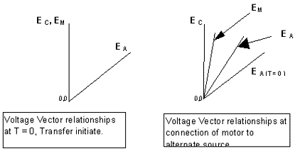
Figure 1. Voltage relationships for near in phase transfer
Figure 2 is reproduced from the Industrial Power Systems Data Book, ref ii. It shows that the phase angle shift of a fully loaded motor, in the range of 200 hp to 1500 hp, will change by up to 60° in the 4 cycles immediately following disconnect.
The phase angle shift is less for lighter loading. This reference states that near-in-phase transfer can be achieved at the first slip cycle within 2 to 4 cycles. The conclusion can be drawn that if the transfer can be initiated as the sources are approaching synchronism and the off time can be held to less than 4 cycles, then successful near-in-phase transfer is achievable.
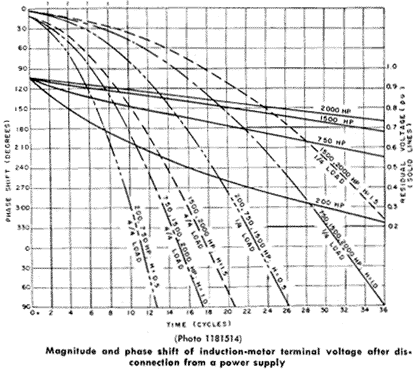
Figure 2. Source Industrial Power Systems Data Book.[i]
The angle of 60° has been cited as a parameter for good reason. Figure 1 assumes that the source and back EMF vectors are of unit length. Since they represent the voltages in consideration, and it is desired to restrict the inrush current to starting current or less, then the resultant of these vectors must be no more that unit value at the instant of reconnection.
This occurs at an angular difference of 60°. For smaller angles, the resultant vector, instantaneous voltage magnitude at reconnection, will be less than unit length. Using the Law of Cosines, the magnitude of the resultant voltage vector can be determined by:
ER2 + Es2 + EM2 - 2 ES EM cosθ
where:
ER - Resultant vector magnitude
ES - Vector magnitude of source motor is transferred to
EM - Vector magnitude of motor back EMF
θ – angle between ES and EM
Experiment has shown that the magnitude of EM is always less at the instant of disconnect than the source voltage. This is readily understood from the circuit model of the induction motor. The voltage transformed to the rotor is the terminal voltage less internal voltage drops such as the IR drop in the stator winding. When the motor is coasting down, the voltage reduces further by the IZ drop across the stator when current is flowing out of the motor.
The motors used in these experiments were driving synchronous generators. Loading was achieved by applying resistive load to the generator terminals. The resistance was changed to vary the load on the generators. The load's rotating inertia was restricted to that of the rotors of the motor and generator. No additional mechanical load was introduced. This was done so as to limit the effects of inertia on the coast down of the motor.
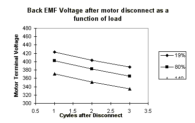
Figure 3. Motor terminal back EMF as a function of motor load at disconnect
Figure 3 is a plot experimentally obtained for a running motor at various loads. Note that as load increase on the motor, terminal back EMF voltage at disconnect decreases. Note further that the rate of decay of voltage is the same for all three cases. The rate of decay is a function of the load that the motor voltage drives during open transition.
Given this significant reduction in back EMF terminal voltage, an angle of greater than 60° can be tolerated. In this case, applying the law of cosines to determine the maximum angle for reconnection at 2 cycles and 3 cycles, respectively, and limiting ER = ES, Θ can be 65° and 66.2° at minimum load and 68.5° and 69.6° at maximum load, respectively.
Successful in phase transfer of motors is not a function of transfer control strategy alone. EM has a frequency as well as a magnitude. The frequency equals that of its source minus the motor's slip frequency during the instant of disconnect. This frequency decays with time and is dependent upon the inertia of the mechanical load driven by the motor.
Higher inertial loads will have longer frequency decay times. As can be seen from Figure 4, back EMF frequency at the instant of disconnect becomes line frequency minus slip frequency. The plot shows that as the load increases, frequency decreases. Additionally, the rate of decay in frequency increases with motor load.
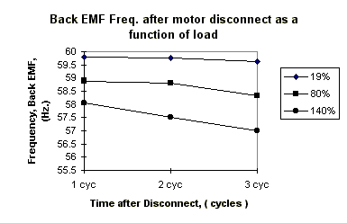
Figure 4. Motor terminal back EMF frequency as a function of load
The actual point of disconnect of a load is obscured without a mindful awareness of load switching dynamics. When a switch interrupts an AC current, an arc is drawn. This arc begins as the switch contacts part and provides a path for continuity of current flow until the arc is extinguished.
The arc is extinguished and disconnect occurs when the current wave goes through a zero cross over. If the voltage at that instant is not sufficient to cause a re-strike of the arc, current flow in the system ceases. However, if the arc is re-struck, current will flow for another half cycle until the next zero current crossover.
In the design of a transfer switch, because the load is being switched between two live sources, a designer will typically design open transition time to assure three zero current crossovers will occur before re-closing the contacts to the other source. This prevents a source to source arc.1 In a 60 Hz. system, the minimum time for three such cross overs is 16.67+ ms. A prudent design would assure a minimum of 16.67+ ms off time in transition. In transferring a load that generates a back EMF with a decaying frequency, there is a limit to just how long that transfer can take and still make reliable in phase load transfer. The environment for successful in phase transfer is better served when the time between the initiating command to transfer and the beginning of contact motion is held to a minimum. Additionally, this transfer time must be consistent. This is revealed by Figure 2.
Given the dynamics of motor load transfer, frequency difference is a major factor in determining successful in phase transfer. It has been established that the normal starting inrush current will not be exceeded upon reconnection of a running motor if the relative phase angle of EM with respect to ES at reconnection is limited to 60° or less.
For the case of a frequency difference between the sources of 2 Hz., the rate of change of relative phase angle is 720° per second, or 0.72V per millisecond. This condition would allow a maximum transfer time of 60° / .72° /ms = 83.3 ms. If the motor had a 3% slip, 1.8 Hz., the total rate of change could be 3.8 Hz. or 1.37° per ms. This would allow 43.5 ms for open transition transfer time. When the arcing time is added to this off time, a transfer time of 60.17 ms will allow for source frequency difference plus slip frequency while still achieving motor reconnection at an angular difference that would limit inrush current to starting current or less.
It can now be concluded that given a consistent and short duration open transition transfer time combined with a control strategy that takes account of frequency difference between sources at the time of transfer initiation, successful in phase transfer of running motor loads can be reliably achieved.
A rather extensive experiment was conducted to confirm this conclusion. The load was comprised of two motor generator sets, 10 hp and 50 hp. These sets were loaded with resistive load banks to produce various load settings for the respective motors.
An alternate variable frequency power source, diesel generator, was operated at frequency difference settings 0.1, 0.5, 1.0, 1.5, 2.0, 2.5 and 3.0 Hz. Load transfer was made in both directions, from the higher to the lower frequency source and vice versa. Three transfer operations were made in each direction for each setting and the results were averaged. Two transfer switches were used. Ratings were 100 Amps and 1200 Amps.
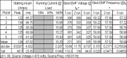
Table 1. Typical data for a given load setting on the MG Set
At the beginning of the evaluation, the motor generator sets were characterized. Table 1 is a representative sample of the tabulated characterization data, highest motor loading. Each motor load was characterized by load setting, power factor, slip frequency, and degree of change. The data was plotted graphically as shown in Figure 3 and Figure 4.
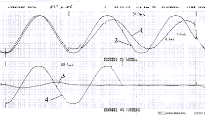
Figure 5. Representative oscillographic plot of inphase transfer event
Each transfer was captured on a four-channel digital oscillograph recorder. Figure 5 is a representative plot. Channel 1 is the motor terminal voltage; channel 2 is the voltage of the source to which the load was transferred; channel 3 is motor line current and channel 4 is transfer switch operator coil voltage.
Several pieces of information were extracted from the recorded oscillographs. That information includes:
- Tcont. - Contact transfer time measured from instant of detectable contact motion to instant of reconnection;
- % ILR - Percent locked rotor current at motor reconnection;
- Δθ - Phase angle difference between source voltage and back EMF voltage at reconnection;
- ΔF - Frequency difference between motor back EMF and source at reconnection.
Several series of tests were conducted. In one series of tests, 150 transfer operations were made with a 100 A ATS and again with a 1200 A ATS. In another test an enhanced software version was used for a total of 81 transfer operations on a 100 A ATS.
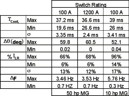
Table 2. Summarized results of in phase transfer operations
The purpose of the investigation was to determine performance of an in phase transfer strategy on a consistently short open transition time transfer switch in transferring a running motor at various loads. Figure 6 is a plot of inrush current magnitude as a function of source frequency difference at the instant the motor reconnects on transfer between adequate sources.
Figure 7 and Figure 8 are plots of relative phase angle between EM and ES for the same conditions, except for different size transfer switches. The plotted points are the average of three transfers at each setting. Figure 9 is a plot of the same conditions as Figure 7 using enhanced software.
The data clearly shows that the criteria for successful in phase transfer of a running motor is met. That criteria being continuous operation and no more than motor starting inrush current.
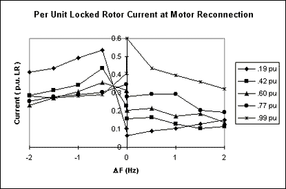
Figure 6. Inrush current compared to locked rotor value at reconnect, 100 A ATS
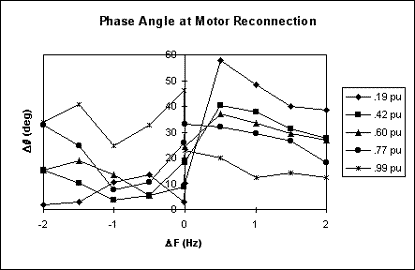
Figure 7. Relative phase angle at reconnection of motor, 100 A ATS
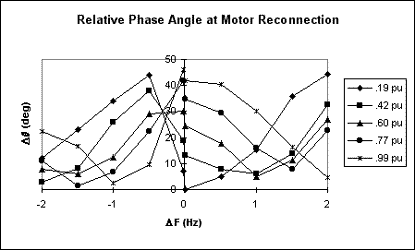
Figure 8. Relative phase angle at reconnection of motor, 1200 A ATS
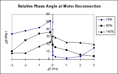
Figure 9. Relative phase angle at reconnection of motor, enhanced software, 100 A ATS
(Back to top)
The transformer
The inrush phenomena of a transformer results from its residual core magnetism. When a transformer is first energized, a transient exciting current flows to bridge the gap between the conditions existing before the transformer is energized and the conditions dictated by the steady state requirements.
For any given transformer this transient current depends upon the magnitude of the supply voltage at the instant the transformer is energized, the residual flux in the core, and the impedance of the supply circuit.ii The value of the residual flux is a function of the physical characteristics of the core and is in the area of 60% of the maximum flux density, βmax. It follows then that, the initial inrush current on transformer energization is a function of the instantaneous angular position of the voltage wave with respect to residual magnetism of the core.
The closer the angular position of the voltage wave is to the residual magnetism of the core, the lower the inrush current will be. The maximum theoretical value of flux density is (βresidual + 2 βmax). This occurs when the transformer is energized when ι would be at a negative peak in the case of Figure 10. It is seen that if the transformer were energized when ι were at zero going negative, coincident with where it was deenergized, normal magnetizing current would flow.
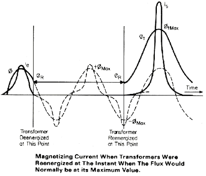
Figure 10. Source: Applied Protective Relaying, Westinghouse Electric Corporation, Relay-Instrument Division, Coral Springs, FL
The maximum theoretical flux density will produce super-saturation in the magnetic circuit. The inrush current for the supersaturated ranges of the wave can be calculated in terms of the air core inductance of the winding and the space flux. The peak instantaneous inrush current, ιmax, can be approximated from:iii
ιmax = 103hAC( βresidual + 2 βmax - 130 )
3.2nAS
where:h -- length of winding in inches
AC -- Cross section area of core
AS -- Cross section area of air core within excited winding
βresidual-- Residual flux density
βmax -- Maximum flux density
n -- number of turns in winding
Transformer inrush currents can be high enough to trip feeder breakers on energization. The duration of these inrush currents can be upwards of 0.5 seconds or longer. As an example, Figure 11 is presented to show experimental results.
This is an oscillographic record of the inrush current to a bank of three 25 kVA transformers connected in Δ – γ, rated 480 VAC primary and energized from the primary side. Phase B demonstrates the highest inrush current at energization in this instance. The peak value is approximately 450 amps. The full load rating of the transformer is 42 amps, peak. Inrush current in this case is more than 10 times transformer full load current.
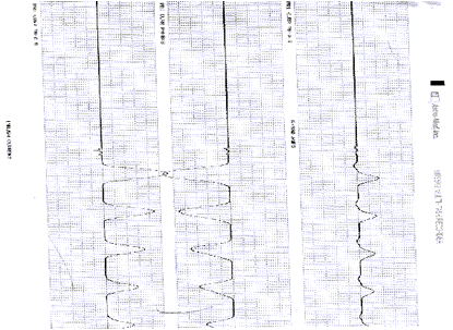
Figure 11. Magnetizing inrush current, 3 phase 25 kVA transformer bank
The issue of magnetizing inrush currents is raised when the critical load is comprised in part of transformer loads. Loads such as uninterruptable power systems and medical diagnostic equipment are in this category. The question becomes, "How is the critical power system desensitized to this phenomena?"
At present, there is no known cost effective means of energizing the transformer at the point of coincident residual flux that will mitigate the inrush problem. Therefore, the designer is left with designing the protective relaying to ignore the inrush phenomena. However, there are some steps that can be taken.
To begin with primary branch-circuit, over-current protection should include a short delay trip function. A suitable setting for most applications would be 6 to 9 x rating for 6 to 9 cycles. At the end of this delay, the inrush would be sufficiently reduced so as not to initiate trip of the over-current protective device. The designer is cautioned to make sure that these settings properly coordinate with the overcurrent protective scheme of the system.
Additional consideration should be given to the energization of these loads from the alternate power supply when it is comprised of on site generators. The relatively high impedance of this power source can cause significant voltage disturbances when large transformers are energized unless steps are taken to mitigate this impact.
While transfer from a dead source to a live source, restoration to the alternate power source on loss of normal service, can not be avoided, transformer magnetizing inrush can be avoided on transfer between live sources by using a closed transition transfer strategy. In this strategy, the two power sources are paralleled under 100 ms.
This precludes transformer disconnect for test, restoration to normal and load demand abatement transfer operations. Where the transfer switch has a consistent and short operating time, closing of the incomming source switch and opening of the outgoing source switch can be achieved in the 100 ms time constraint. (Back to top)
Adjustable speed drives
The adjustable speed drive is a subset of the UPS, absent the input transformer. Figure 12 is a simplified schematic of the front end of a typical adjustable speed drive. It shows a combination of SCRs and diodes feeding a DC bus. The DC bus has capacitive (and occasionally inductive) filtering that feeds the inverter motor drive.
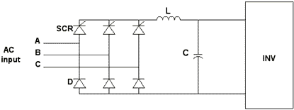
Figure 12. Typical input circuitry of an Adjustable Speed Drive
The SCRs are controlled so that at turn on of the drive, the gate drive slowly advances from zero cross over to limit inrush current as the capacitors are charging. When the DC bus achieves the regulated voltage level, the inverter is then turned to start, accelerate and control the mechanical load.
From that point on, the SCRs are gated on to maintain the DC bus voltage at the regulated level. The capacitance in the input stage provides the ride through that Key[i] determined to be approximately 5 cycles. Recognizing that the ASD must ride through the normal fluctuations and outages occurring on the normal power supply, the SCR control is designed to limit inrush current for capacitor recharge so that the SCRs are protected against damaging inrush currents.
When the ASD is a load in a transfer scheme, since it has a 5-cycle ride through, concern need only be given when the transfer between live sources has an open transition transfer time in excess of 4 to 5 cycles. When the transfer switch has an open transition transfer time of less than 4 cycles, there should be no ill effects in transferring the ASD between live sources. When transferring from a failed source to an alternate source, the ASD will have already gone through the shut down cycle and will require no more than normal start. (Back to top)
Conclusions
The burden of restoring automated critical loads to service after a power loss is no more difficult than starting them. The burden of transferring these loads between adequate sources, restoration to normal power after an outage or transferring to the alternate source for load demand abatement or system testing can easily be orchestrated with the proper control and switching strategies.
Where it is undesirable to shut loads down for switch over, short duration open transition transfer times, 2 to 3 cycles coupled with in phase transfer control strategy is suitable for application to motor loads.
For inrush loads, i.e. transformers, careful design of the over-current protective scheme and closed transition transfer can mitigate the effects of inrush currents. The ASD loads can be transferred effectively provided the open transition transfer time is less than 4 cycles. Thus, it is demonstrated that a proper control strategy combined with a consistently short-duration, open-transition transfer time is a suitable transfer strategy for machine and other inrush loads. (Back to top)
1 The environment for a source to source arc is virtually non-existent when in phase transfer is used. This is due to the source voltages being close to synchronism when transfer is initiated. There being reduced voltage potential between the sources at disconnect, reduces the arc driving voltage.
i Sec. 813, Industrial Power Systems Data Book, General Electric Co., Schenectady, NY
ii Electrical Transmission and Distribution Reference Book, Westinghouse Electric Corporation, East Pittsburgh, PA
iii Blume, F. L., et al, Transformer Engineering, John Wiley & Sons, New York, NY
About the Author: Daley has been with ASCO since November 1965. In his tenure, he has served in several product oriented engineering and marketing capacities dealing with power control systems, the most recent being director of engineering for switchgear. He currently serves as division engineer for ASCO's switch division. To contact Daley, 973-966-2474, jdaley@asco.com. (Back)
Subscribe to our free e-mail newsletter.
Click for a free Buyer's Guide listing.
