Boiler Tube Leak Detection at Conemaugh Generating Station
By Trudy Bryson, Triple 5 Industries
Abstract
In December 1992, the PENELEC-GPU corporate research group purchased the AMS-1 Acoustic Monitoring System for installation on Unit 1 at Conemaugh. Unit 1 is an 850 MW, 3,675 psig, CE boiler commissioned in 1970.
The AMS system uses waveguides and sensors mounted on the boiler membrane and peg finned tubes to listen for leak noises. Coax cable connects a preamplifier, near each waveguide location, to the system cabinet, using cable runs as long as 1,500 ft. The AMS, located in the cable spreading room, contains solid state circuitry to amplify and filter the incoming signals, and software to trend for increased acoustic energy in the 1.7 HKz to 90 KHz and 20 Hz to 1 KHz ranges. The system signals an alarm when the acoustic energy caused by a leak exceeds a preset threshold for a predetermined amount of time.
The goal of the project was to assess the reliability, effectiveness and cost benefits of leak detection equipment using the recently developed metalborne waveguide technology. In May of 1994, as part of the project, two metalborne waveguides located next to two airborne waveguides in the economizer section were activated to compare the sensitivity of these two different technologies.
During the five-year project, several leaks occurred in Unit 1, with the AMS system giving the operators the only indication that there was a problem in the boiler. In addition, a leak occurred in the economizer section during the time that the side-by-side airborne and metalborne waveguides were instrumented.
The results showed that metalborne waveguides were more sensitive than airborne. Also, metalborne waveguides proved to be less expensive to purchase and to install, and more reliable than airborne waveguides. As metalborne waveguides do not require an existing opening in the furnace, their use in the lower furnace proved invaluable.
Between 1995 and 1997, the equipment was upgraded to the AMS-2 Acoustic Monitoring system and serial connection to the DCS for operator interface was completed. At the time of this report, the Conemaugh station has one acoustic monitoring system that monitors Unit 1 and Unit 2. Each boiler is instrumented with eight metalborne waveguides with accelerometers.
In the future, the station plans to add more sensors to both units, with 28 being the optimum number. The additional sensors will expand the coverage to include every section of both units. The AMS-2 system can monitor a maximum of 192 inputs on as many as eight different boilers.
Leak Detection Theory: How Does It Work?
The system is designed to detect very small steam leaks in pressurized systems, such as power boilers, recovery boilers and feedwater heaters. On a boiler, it performs this function by continuously measuring the internal sounds using piezoelectric sensors. The sensors are located in every section of the boiler and number between 12 and 40 per unit depending upon the size of the boiler. The sensor converts the vibrations caused by a tube leak to a voltage, which the system logs and trends.
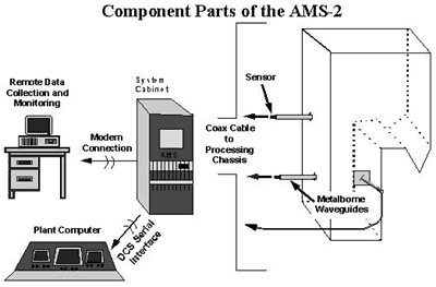
The electronic circuitry filters and amplifies the sensor signal in the frequency band between 1.7 KHz and 11 KHz, where there is the greatest difference between the leak signal and the normal background noise. Also, at Conemaugh, the 20 Hz to 1 KHz band is also monitored to determine the sensitivity of this range to leak noises. In addition to trending the acoustic signal for each sensor, the system trends auxiliary parameters such as load (MW), makeup flow, gas flow, and reheat pressure. These parameters are useful in determining the effect of normal operating conditions on the background noise in the boiler. The operators at Conemaugh interact with the system directly, as well as through a DCS serial interface.
The AMS system at Conemaugh uses metalborne waveguides to guid leak noises to the sensor. A metalborne waveguide, or Sounding Rod, is a 3/8-in. diameter X 12-in. long, stainless steel rod that is welded to boiler tube membranes and boiler casing. It has a chisel tip at the boiler end to facilitate welding and a tapped hole at the opposite end. The high temperature sensor attaches to the tapped end with a 10/32 stud. The sensor is specifically designed to be minimally affected by outside boiler noises.
In areas of the boiler where there are peg-finned tubes, such as the economizer, a 12 in. X 12 in. X ¼ in. SS plate is attached on the hot side to act as a sound collecting plate. The Sounding Rod attaches to the center of the plate and extends through the fins to the outside of the boiler lagging. The Conemaugh Station was the first to use this experimental approach for Sounding Rod attachment to non-membraned, steam cooled walls.
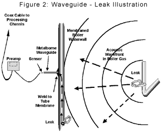
Steam leak noises propagate through the boiler gases and through fused metal pathways. The AMS system uses metalborne waveguides with acoustic emission snesors to detect both types of leak vibrations. Figure 2 illustrates how metalborne waveguides detect both airborne and metalborne leaks.
Airborne leaks: If there is a leak inside of the boiler, such as in the superheater, reheater or the economizer, the vibrations from that leak produce acoustic wavefronts that travel through the gases and hit the boiler wall or waveguide plate. The wall/plate acts like a diaphragm, vibrates and causes the sensor to vibrate, producing a change in voltage. The system amplifies, filters and analyzes that voltage and gives an alarm if the signal is above a preset alarm threshold for more than a preset time delay.
Metelborne leaks: If there is a leak in a water wall, either internal or external to the boiler, that leak produces vibrations that travel across the tubes and across the membranes to the sensor. The sensor converts the vibration to a voltage that the system amplifies, filters and analyzes. The system alarms if the signal is above a preset alarm threshold for more than a preset time delay.
How to Handle Sootblowers
The noise produced by sootblowers is very much like the noise produced by a steam leak. The system uses time delay to differentiate steam leaks from sootblowers. The time delay for each sensor at Conemaugh is set to 30 minutes. The long retracts at the station operate for about 10 minutes.
When a sootblower is operating and a sensor responds to the noise, the time delay clock for that sensor starts counting down. When the sootblower shuts off, the background noise in the boiler returns to normal (assuming there is no leak in the boiler), and the time delay clock resets. When the next sootblower or sootblower pair starts up, the 30 minute time delay clock for any sensor that hears the blowers starts counting down again. The system gives an alarm when the time delay clock times out past 30 minutes, which only occurs if there is a continuous, unusual noise in the boiler, like a steam leak or a stuck sootblower.
Waveguide Technologies
Airborne vs. metalborne waveguides: The first systems that Triple 5 supplied for power boilers used airborne waveguide technology. An airborne waveguide is usually a 1-in. or 2-in. diameter, stainless steel tube, about 18 in. long, curved to a 90-degree sweep. One end of the tube mounts to the boiler wall at locations where an opening exists, such as an inspection or manway door. The sensor mounts in the other end.
The waveguide, or listening tube, carries the acoustic wavefront caused by a leak to the sensor. The inherent problem with this technique resides in trying to keep the tube open. Invevitably, the waveguide plugs with ash, which blocks the acoustic pathway to the sensor, decreases system sensitivity, and creates maintenance problems for boiler personnel who must unplug the tube.
Knowing these problems, Triple 5 looked for a way to detect leak noises without using airborne waveguides. In 1989, we magnetically attached a Sounding Rod to the waterwall of a recovery boiler. The success we experienced lead to the installation of Sounding Rod waveguides on Unit 1 at Conemaugh in early 1993.
Research Efforts at Conemaugh
Triple 5 conducted several experiments on operating recovery and power boilers to assess the sensitivity and reliability of metalborne waveguides. We compared the response of airborne waveguides mounted next to metalborne waveguides by using sootblowers as simulated leaks. Figure 3 shows the voltage response to the noise created by 17 pairs of sootblowers for metalborne waveguide #8 compared to airbone waveguide #17.
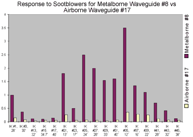
Waveguides #8 and #17 were located side-by-side on the front wall of a B&W recovery boiler, 700 tons/day, 1,400 psig. Before data collection, we thoroughly rodded the airborne waveguide. The response of the metalborne waveguide, was, in some cases, 10 times greater than that of the airborne waveguide.
The horizontal axis identifies the sootblower (IK) number and gives the distance in feet between the sootblower and waveguides #8 and #17.
Our positive experience with metalborne waveguides on recovery boilers led us to try the same method on power boilers. At Conemaugh, we conducted similar side-by-side comparisons and were lucky enough to detect an economizer leak in Unit 1 May 28, 1994. Figure 4 shows a 2.5-hour time frame versus amplitude of signal for the airborne and metalborne waveguides that detected this leak. The response of the metalborne waveguide was about two times greater than the airborne.
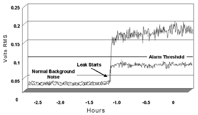
2.5-Hour History Trend for an Economizer Leak: Metalborne vs. Airborne Guides
Advantages of Metalborne Waveguides
Metalborne waveguides provide several advantages over airborne waveguides.
- Metalborne waveguides are one to three times more sensitive to steam noises than airborne waveguides.
- Metalborne waveguides on water walls detect tube leaks that are both internal and external to the furnace.
- Metalborne waveguides can be located almost anywhere on the boiler. They are not limited to existing boiler openings. They can detect tube leaks in lower furnace walls.
- Metalborne waveguides detect leak noises, which travel through the boiler gasses as well as those that travel through fused metal pathways.
- Metalborne waveguides cost less to purchase and less to install.
- Metalborne waveguides reduce system maintenance.
Evolution of Equipment at Conemaugh
The station purchased Sounding Rods in October 1992 for installation during the upcoming outage for Unit 1. They installed 18 rods on Unit 1 and in December, Triple 5 delivered the AMS-1 Acoustic Monitoring System with enough hardware to monitor four locations. The filter bands were set at 1.7 KHz to 13 KHz for the low frequency filter and 35 KHz to 180 KHz for the high frequency filter. In December of the following year, Triple 5 delivered enough hardware for four more locations, and the station instrumented two airborne waveguides along with two more metalborne locations for the side-by-side comparison. In December 1994, the station expanded the system to include eight sensors on Unit 2.
Triple 5 continued to develop the AMS system, and in July 1995, it upgraded the AMS-1 to the AMS-2 Acoustic Monitoring System. The AMS-2 featured software control of gain and time delay, and included the software needed for serial interface to the Honeywell DCS. In addition, the high frequency bandpass filters were changed to an experimental tandem filter in the range of 20 Hz to 1 KHz. This bandpass is much lower than traditionally used for leak detection, but Triple 5's initial test showed great sensitivity in this range, and the station agreed to participate in an on-line trial.
In July 1996, Triple 5 conducted training classes for operators. We explained leak detection theory, described the features of the system, and encouraged operators to perform a daily review of long-term trends, looking for gradual, upward trends indicative of a small leak that is growing.
At the time of this writing, Conemaugh has instrumented eight locations on each unit. The future plans include expanding the system to a total of about 24 sensors on each unit. The increase in the number of sensors will help detect leaks when they are small and locate leaks with added accuracy.
Leaks at Conemaugh
The following descriptions of tube leaks occurred in Units 1 and 2 at Conemaugh.
Leak 1: The tube leak occurred in the lower furnace of Unit 1 in mid-April 1994. The station had recently installed a new lower furnace and the staff was concerned about possible field weld defects. Upon examination of the data during a modem connection to the system, Triple 5 engineers saw a steady increase in the low frequency trend and the high frequency trend for sensor #9.
The sensor was located in the lower furnace, and the trend had been increasing for about two weeks. Plant personnel turned off all sootblowers and opened inspection doors to try and locate the source of the acoustic energy. The leas was under the slope, spraying downward and was estimated to be flowing at about two to three gallons per minute. By the time the shutdown was completed, the leak was flowing at about 60 to 70 gallons per minute. There was no other control room indication of a leak.
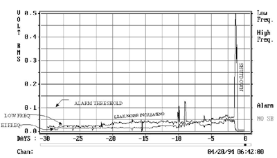
30-Day History Trend for Sensor #9: High and Low Frequency Trends
Leak 2: The tube leak occurred in the upper economizer of Unit 1 during the time period for the side-by-side comparison of the metalborne and airborne waveguides. The figure above is the 2.5-hour trend that shows the beginning of the leak that started at 19:10 May 28, 1994. The metalborne waveguide and sensor responded with an increase in RMS voltage from 0.05 V to .175 V. The airborne waveguide and sensor responded with an increase in RMS voltage from 0.05 V to only 0.90 V. The alarm from the airborne waveguide sounded about three hours after the metalborne waveguide.
The unit was taken off line for repair at 19:40 May 30, 1994. There were two leaks, each about 3/8 in. in diameter, 27 ft from the sensors. One was on the top of the economizer, and the other was in the steam-cooled wall.
The detection of this leak was unique in two respects. One, it occurred in the section of the boiler selected for the side-by-side comparison of metalborne and airborne waveguides, resulting in data confirming the enhanced sensitivity of metalborne waveguides. Two, it was the first leak ever detected using a waveguide plate and Sounding Rod.
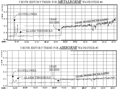
5-Hour History Trend for Metalborne Waveguide #4 and 5 Hour History Trend for Airborne Waveguide #3
Leak 3: The tube leak occurred in the lower furnace of Unit 2 when it was equipped with only four metalborne waveguides and sensors. The leak was a 1-in. long radial crack in the lower end of the division wall where it penetrates the slope. The crack was about 46 ft from metalborne sensor #9 and was blowing into the right side, B Furnace. The vibration, caused by the leak, traveled across the tubes and tube membranes to the sensor mounted on the metalborne waveguide.
The operators had not yet been trained on the use of the AMS system, so as part of the research project, Triple 5 engineers monitored the system vial modem. On Sunday morning, Nov. 13, 1994, a Triple 5 engineer informed the plant personnel of a possible leak condition. Operations confirmed the presence of a leak upon boiler walk down and by noting small increases in make-up. The shutdown was planned for that evening. With the early detection of the leak, the engineers at Conemaugh Station estimate a cost benefit of about $125,000 based upon saved downtime and avoided secondary damage.
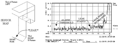
10-Day Trend for Sensor #9: Shows the increase in acoustic activity. Sensor #8, 55 ft away from the leak, also signaled an alarm.
Leak 4: The tube leak occurred in the lower furnace of Unit 1 in November 1996. It was the Wednesday before Thanksgiving, a typical time for an untimely tube leak. The operations team leader (Dennis Shaulis) saw a jump in the signal level for sensors #3 and #4. Upon opening an inspection door, he could hear the leak. He alerted the operators who say that make-up was normal at about 20 gallons a minute. There were no other indications that a tube leak existed except for the alarm on the AMS system. Operations decided to continue to run through the holiday.
On Friday, make-up was about 50 gallons a minute. The unit was taken off line and upon hydro, personnel found several weepers. The primary leak was 30 ft below sensor #4, on the slope just at the point where it meets the wall. Sensor #3 was 40 ft away.
From an instrument point of view, the most significant part of this incident was the response of the experimental, tandem filters. The tandem filtered signal for both sensors showed a greater response to the leak condition than the standard, low frequency filter. In particular, the response of the tandem filter for #3 was about 6dB greater than the standard, low frequency filter.

30-Day Trend for Sensor #3: Low Frequency and Experimental Tandem Filter here.
Conclusion
Tube leaks are the number one cause of forced outages in power boilers. At the Conemaugh Station operated by GPU-Genco, early detection of small tube leaks provides the time needed to plan outages during periods when demand is low. The data logging capability of the leak detection system provides the means to monitor the growth of leaks. In addition, the metalborne waveguide technology has proven to be effective, reliable, sensitive, and virtually maintenance free.
During the five years of operation, this utility has used the AMS to early detect about 24 leaks and estimates the total cost benefit to be in the thousands of dollars by preventing excessive downtime and secondary damage.
About the author: Trudy Bryson, with Triple 5 Industries, can be reached at 242 Route 156, Yardville, NJ 08620, trudy@triple5industries.com, 609-585-5588.
